- Products
SensorsMicrophone kitEar simulatorMouth SimulatorShakerPreamplifiersSpeed SensorsSensor AccessoriesMeasurement microphoneArtificial MastoidPlane SourceVibration SensorsSimulator HeadCalibratorDynamic ForceInstrumentsPM SerialsLR SerialU SerialsN SerialsWind Noise SimulatorSound Level MetersRotary tablesSoftwaresBuildGoAudioExpertVQBenchStingerSIO LabMagnumBT LabSignalBenchAccessoriesAuxiliary InstrumentsAnechoic ChambersCablesInstallation kits
- Solutions
- Technology
- About Us
-
 CN
CN
Uplink Bone Conduction Technology Testing
Project Overview
Beamforming - Directional enhancement technology that focuses the microphone's sensitivity in a specific direction to capture the speaker's voice more clearly.
Adaptive Filtering - A technique that adjusts the filtering process in real-time to better distinguish and isolate the speaker's voice from background noise.
Bone Conduction Technology - A method that uses vibrations conducted through the bones of the user's head to pick up their voice, which can help in noisy environments by providing an additional source of voice signal that is less affected by ambient noise.
An Introduction
Overview of Uplink Bone Conduction Technology
Bone conduction can be divided into uplink and downlink bone conduction communication technology. The former is to enable the other party to hear clearly, and the latter is to enable themselves to hear clearly. Today, we mainly introduce the technology of uplink bone conduction of the former
In this article, we discuss uplink bone conduction.
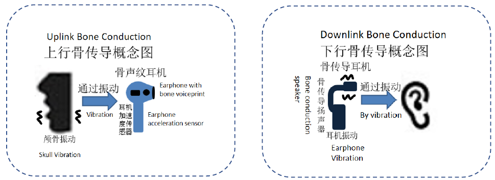
In the process of talking, the sound of our own speech is the useful signal we really want to transmit, but in addition, there are various noises generated by machinery and equipment, wind, surrounding people, etc., which can be called useless signals.
The essence of the uplink bone conduction technology is to transmit the content of the call by collecting the vibration signal of the cheek. Because the ambient noise conduction medium is air, the vibration of cheek is directly collected by the acceleration sensor to achieve the effect of of noise filtering in air.
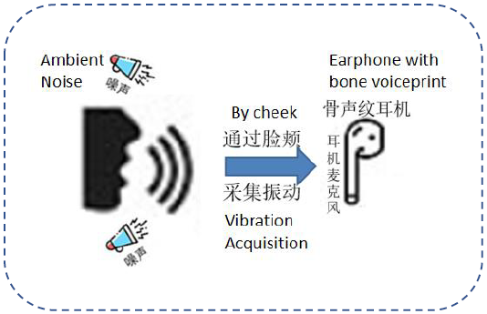
When we speak, in addition to the vibration of the face, the vibration of the nose bridge is also stronger. So, this technology is not only used in the field of headphones but also can be used in VR or AR smart wearable devices to improve the effect of calls.
The testing of uplink bone conduction technology in call can be divided into three parts: IQC chip incoming test, Bone voiceprint test in semi-finished product stage, and Bone voiceprint test in finished product stage. These three tests are all supported by our system compatibility.

If the defective products flow into the manufacturing process, they may result in manufacturing product being dismantled to replace parts, or scrapped directly, which will cause huge economic losses.
The incoming IQC chip can be divided into chip with digital format microphones or chip with conventional analog silicon microphones from the signal type. Let us analyze the working principle from the architecture diagram.
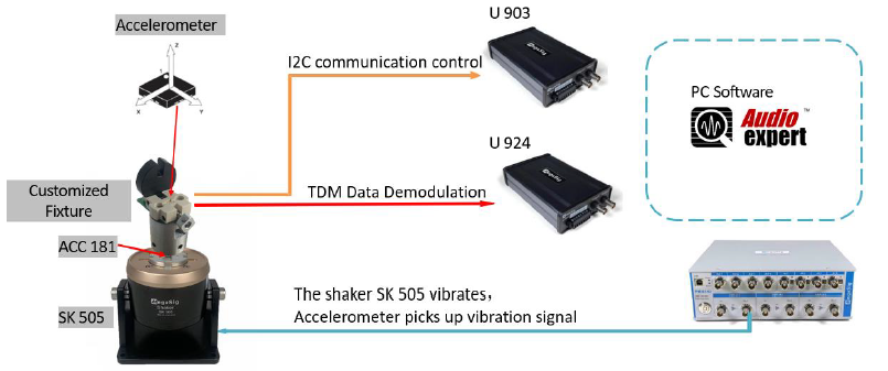
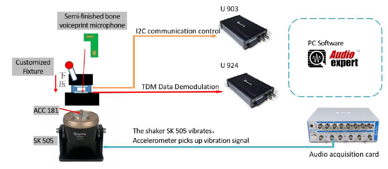
The analysis and introduction of the first kind of IQC incoming chip with digital format microphones test system architecture diagram: PC software AudioExpert control the acquisition card push a signal to the exciter SK 505 making it vibrate. The IQC chip's incoming material corresponds to the customized fixture pin, communicating with U903, demodulating the received vibration signal by U 924 in digital TDM format, and then transmits it to PC software AudioExpert for analysis.
The first method: Analysis and introduction of the IQC incoming digital chip microphone testing system structure. The PC software AudioExpert is utilized to output a sweeping frequency signal to the vibrator SK 505, inducing it to vibrate. The IQC incoming material chip is connected to the custom fixture pins, communicates with U 903, and demodulates the received vibration signal into a digital TDM format at U 924, which is then sent to the PC software AudioExpert for analysis.
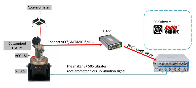
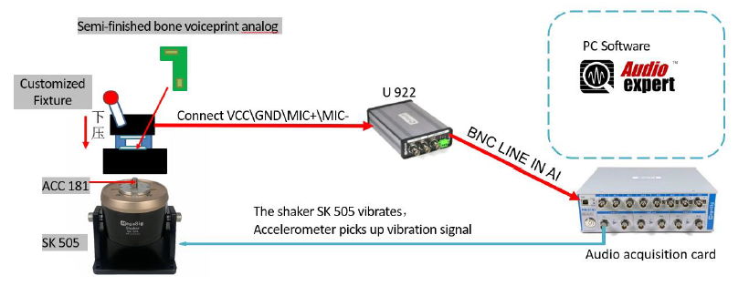
The second method: An analysis and introduction of the IQC incoming analog silicon microphone testing system structure. The PC software AudioExpert dispatches a sweeping frequency signal from the audio acquisition card to the vibrator SK 505, causing it to vibrate. The four points corresponding to the custom fixture pins are extracted and connected to U922. The semi-finished bone conduction microphone sends the signal back to the audio acquisition card through U922, which is then analyzed by the PC software AudioExpert.
When the acceleration sensor is attached to PCBA, it may have a poor contact caused by false soldering, which may lead to sometimes be on or off. So it is also very important to conduct test for semi-finished bone voiceprint.
The bone voiceprint test of semi-finished products, like the incoming IQC test, is also divided into chip with digital format microphones or with conventional analog silicon microphones in terms of signal types.
The chip with digital format microphones is through I2C communication and TDM format data demodulation, so the overall test logic can refer to the IQC incoming chip with digital format microphones.
The second form of semi-finished bone voiceprint analog silicon microphone testing system architecture diagram, the overall test logic can refer to the logic of IQC incoming chip with analog microphones test system.
After the test of incoming materials and semi-finished products, it comes to the part of dispensing and assembling the earphones. In this case, the position of the microphone may deviate from the designed position during assembly and rotation, or more or less glue is applied at the place where glue is needed, which will affect the effect of the microphone. And it is necessary to test the finished product after assembly.
The following is the analysis and introduction of the structure diagram of the finished bone voiceprint earphone test system. The finished bone voiceprint earphone is tested by wireless transmission:
AudioExpert -> Acquisition card AO -> vibration exciter SK 505 -> Internal acceleration sensor of the finished product -> SPP/HFP protocol of Bluetooth dongle -> AudioExpert.
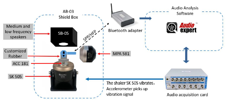
One thing to note is that in the finished earphone with bone voiceprint, the bone voiceprint microphone and the other normal microphones exist independently of each other. So, the test system also needs to be equipped with other hardware that can test the normal microphone, such as: SB-05 speaker, AM 581 artificial mouth.
Configuration List
About Us
Products
Solutions
Technology
Join Us
Contact Us

Copyright © 2014 MegaSig. All rights reserved. 版权所有 粤ICP备15009411号
